CVRSSP
Industrial Vision System
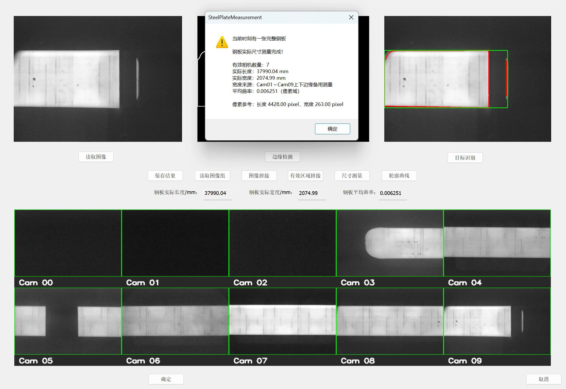
A ten-camera vision system that finds a steel plate, measures it in millimetres and draws its contour.
- C++
- OpenCV
- MFC
- Image Processing
- Year
- 2026
- Role
- Design, implementation and testing
- Context
- Programming Practice, Wuhan University
- Platform
- Windows · C++ · MFC · OpenCV 4.10
Background
Plate dimensions matter at every stage of steel production — rolling, cutting, storage and inspection. Measuring by hand means stopping the line or touching the plate. Machine vision can measure without contact, but only if it copes with real images. CVRSSP simulates that online measurement: given images from ten cameras along a production line, it finds the plate, measures it in millimetres, draws its contour and keeps a record.
Challenge
Real images are messy. A method that works on one sample breaks on the next.
Uneven light
Every camera sees different brightness and contrast, so no fixed threshold fits them all.
Occlusion
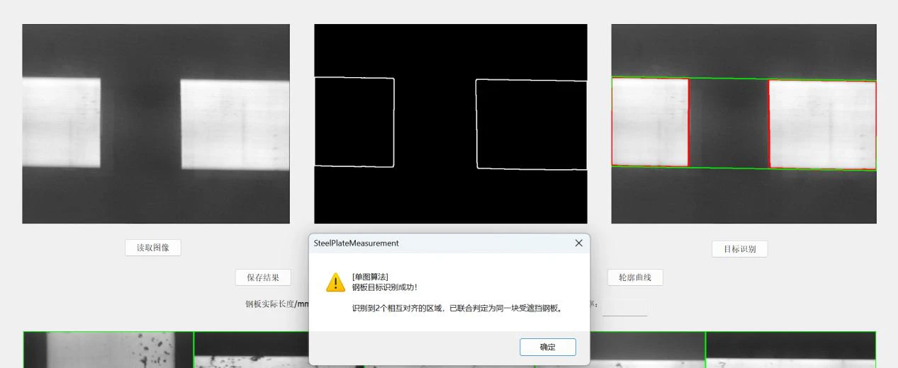
Equipment cuts vertical black gaps through the plate and splits it into separate regions.
Partial views
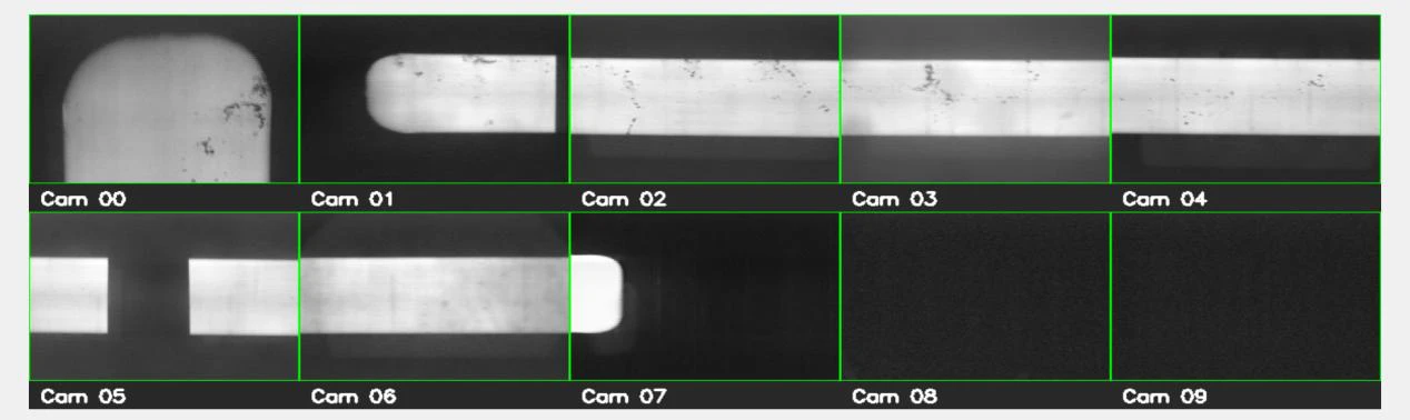
Some cameras see no plate at all; the plate’s ends may cover only a few pixels.
Pixels are not millimetres
Ten views must be tied to one physical coordinate system before any length means anything.
Solution
One consistent pipeline, from raw images to millimetres — where every module agrees on which cameras can be trusted.
01
Adaptive segmentation
Gaussian smoothing and Otsu thresholding let each image choose its own threshold; small morphological opening and closing clean the mask without filling real gaps.
02
Reliable views
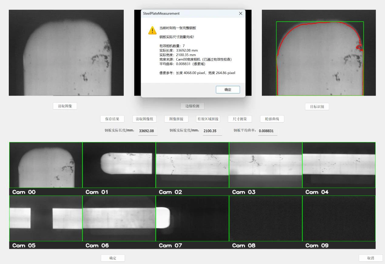
Each camera’s candidate region is scored on contrast, valid columns, thickness and centre stability. Only reliable views are stitched, measured and drawn.
03
Occlusion repair
Vertical gaps inside the plate are found column by column and repaired by interpolating its top and bottom edges — only when every condition holds, so real plate ends are never ‘repaired’.
04
Completeness
The head is checked only in the first reliable camera, the tail only in the last. The system reports whether a whole plate is in view without blocking any other measurement.
05
From pixels to millimetres
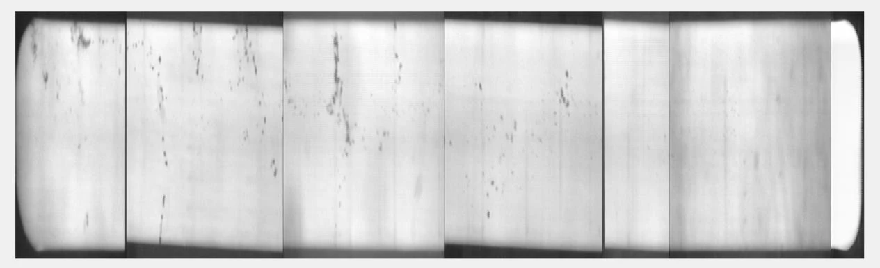
Each camera’s 3×3 homography maps pixels into one world frame. Length is the global span of the plate’s centre line; width is a median across rows, with a backup from the other cameras and a cross-check between them.
06
Contours and records
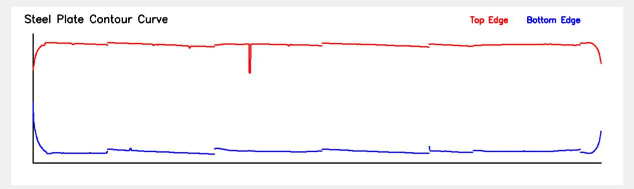
Top and bottom edges are aligned across cameras, gaps filled and spikes smoothed, then drawn as curves. Results are saved as UTF-8 CSV.
Technology
C++
The core application — about 6,700 lines in the main dialog alone.
MFC
A dialog-based interface: three image panels, controls and message handlers.
OpenCV 4.10
Thresholding, morphology, contours and stitching.
Homography calibration
Ten calibration files map every camera into one world coordinate system.
My contribution
- Requirements analysis and the overall architecture
- The full image processing and measurement pipeline
- The MFC interface and its message handlers
- Calibration loading and exception handling
- Twelve functional tests — normal, occluded, partial and background-only cases
- Four iterations, from pixel measurement to calibrated millimetres
Reflection
My first version used a fixed threshold and the largest contour. It worked on a few images and failed on the rest. Industrial vision, I learned, is not about tuning one sample — it is adaptive methods, robust statistics and conditions that hold together. It also taught me what I cannot claim yet: without plates of known size, the pipeline can be verified, but its accuracy cannot. That is the next step.